Arduino is not only a fabulous circuit board, but it is also it’s own language with its own grammar and syntax rules. Using the Arduino basics course from Stan Winston School of Character Arts, I was able to program my Arduino Uno board to do some very simple functions.
Such as:
Programming a buzzer to make sound,
https://www.instagram.com/p/Bc2wpS1DkmI/
Programming a servo to move,
https://www.instagram.com/p/Bc2zdigDI8r/
Making my first code!
https://www.instagram.com/p/Bc5f4qmjA_9/
Which has all lead towards me assembling my first actual robot!
I am calling my robot Rosie after the robot in the Jetsons. There are not enough female robots in popular culture and my long term goal is to eventually have Rosie talking like Rosie from the Jetsons! My Rosie is a 2 wheel drive platform from Jaycar, with an ultra-sonic sensor on the front so that she avoids obstacles. Assembling just the platform was tricky as the instructions were hard to find and not linked in the assembly instructions for the whole robot!
The first modification I want to make to the robot is to add a switch so I can turn her on or off. At the moment, I can only turn her off my removing a battery from the battery holder. I also want to experiment with the robot on different surfaces. I was noticing during the first drive that, the wheels got stuck on the thick nylon carpet in my house. I want to compare how Rosie runs on low pile carpet, tiles, and concrete.
What I haven’t been able to achieve yet is to take the Uno board and several other components and write custom code for it yet. So far, I am relying on code that is available in the Arduino Library or on project sheets. My next experiment for Rosie is to add a line trace module to Rosie’s base chassis and see if she can follow a line. My next experiment in coding is to see if I can combine a button press input to a potentiometer and make a joystick work.
In 2018, I will be teaching stand alone STEM classes instead of puppetry. First thing I want to say is I don’t like the acronym STEM which stands for Science Technology Engineering and Mathematics. I prefer STEAM with the A standing for the Arts. Creativity is a very important component when solving real world problems, and in STEAM, creativity is included under A for Arts. For the purposes of this blog, I will refer to the new course as STEAM. So, if you prefer to leave the A out, that’s fine, but I will be all inclusive and call it STEAM.
I have never taught STEAM as a subject before. I have taught many students and colleagues a great deal about using technology to solve problems in teaching and learning but not within the framework of STEAM. I have also used a great many principals of STEAM within my puppet building, through project based learning, iterations and 3D printing. I will be teaching stage 4, which so far, has no program or resources that I am aware of, that can guide my preparation over summer. My school does have access to the amazing iSTEM Syllabus and online resources but the course I am teaching cannot overlap that sensational course.
So what am I doing to prepare myself for an unknown course?
I am creating a STEAM pinterest board of activities and classroom organisation which might help me in the year ahead.
I bought an Arduino starter kit from Jaycar Electronics to start learning how to code my own robots. The best part is I can apply this learning to my puppetry to make my first animatronics move using coding!!!!!!
My Arduino Learning kit with everything to create my first robots!
I am using the Stan Winston School of Character Arts course on Arduino Programming Basics to help me understand the potential that is within this kit.
I have completed my first little project of making an on-board LED light turn on and off by pressing a button! Here are the instructions from Arduino’s website!
Over the last ten weeks, I have been teaching green screen filming to a wide range of faculties at my school. We have had multiple classes in English, Sport, Commerce, and Geography come through and use the green screen. Originally, this started when faculties kept borrowing my green fleece fabric for puppet making to use as a green screen with limited success. Fortunately, I found in a resource catalogue a proper green screen kit with 4 soft box lights which I purchased for my school.
I also purchased a new camera kit for the filming that we are doing at the school for the various projects the school is involved in regarding Teacher Professional development and student teacher experiences. The camera kit contains a XA35 Canon professional camera, a boom microphone, a camera mounted microphone and lapel microphone. Combining the two kits, also gives students an opportunity to use professional equipment, and for me, the opportunity to use professional grade equipment to continue practising my monitor Puppetry skills.
When all the equipment arrived, and I started setting it up, the first thing I needed to learn was how to light the green screen properly. I found a wonderful Lynda.com course that helped me understand how to light the screen properly.
Given the number of students who wanted to film using wide shots, it became necessary to purchase a matching additional green screen from Fotogenic to use as a green floor mat.
I was very surprised that the green screen kit bags did not have built in storage space for the actual screen. I feel that it is very important to keep both of the green screens clean and store it tidly with its frame. I ended up purchasing a Gurli cushion cover from Ikea. It is a perfect size for storing both of the screens folded neatly. It’s also bright green, making it very easy to spot in the storeroom.
The scariest thing about the green screen setup is how easily the lights can fall over and the globes inside smash. When the globe smashed, I was worried that the large 125W globe would be very expensive to replace. I was pleasantly surprised when the replacement globes from Fotogenic were less than $40. To prevent the light stands falling over in the future, I will be purchasing the appropriate sandbags for the lights so they are less likely to tip over when knocked.
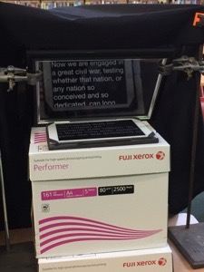
The next amazing thing I learnt while creating the green screen filming kit was how using a teleprompter really helped improve student focus and performance while on camera. The idea for adding a teleprompter came from observing the performance of a year 8 student who is a public speaker and debater. His group was creating a mock- news report, and this student was the news anchor. He delivered all of his lines off the cuff, with enormous confidence, almost directly into the camera. If we had a teleprompter, his performance would have shifted his eye focus directly into the camera, making it professional.
Given in this day and age of ask google and learn from YouTube, I found a number of tutorials online that allowed us to use a school iPad as the prompter display, an old picture frame, 2 science retort stands, a paper box with lids and some black fabric.
The teleprompter apps we have been using is called Teleprompt+3 which is a paid app that works with Apple Watch. This app is great because it links directly to Dropbox and Google Drive, so students could share their script with me and I could bring it up on the iPad with very little delay. The other app we have been using is Parrot Teleprompter which is a free app. Parrot works very well, and I copy the scripts using email or the google drive app and paste the contents into the app. Both apps are easy to use, the speed of the prompter can be changed for the student, as well as the colour and size of the text. In class, we used both an iPad Air2 and a IPad Pro. The most challenging part of the teleprompter setup we were using, was that we could not change the height of the prompter easily. The deputy principal was really excited at how I had created my own prompter, that he wants me to purchase a professional prompter for the school filming kit on an adjustable stand!
Here are some examples of the fun I have had filming with the students at my school:
https://www.facebook.com/MacquarieFieldsHS/posts/1951851818203471
https://www.facebook.com/MacquarieFieldsHS/posts/1915277931860860
All I can say is wow! It works- it’s alive!!!!! I have 16 vertebrae and 8 are moving precisely like they are supposed to! Stage 1 of the tentacle- from the tip to vertebrae 9 is moving and curling. However, for some reason, stage 2 is barely moving. Current working theory is that the brake cable housing I am using is too stiff to allow the stage 2 mechanism to move at all. I may have to make another base plate that has no large passage holes and screw all the brake cable housings into that so that the bare cable is running through the passage holes of the actual tentacle.
I am still waiting for more set screws to arrive so I can finish attaching all the vertebrae and the tail tip. While I am waiting, I have started designing the next mechanism!!!
I have started assembling the tentacle! After printing one of the vertebrae, I held it up to a puppet that it could be used for, and I found that the diameter of the vertebrae was too wide. So I reduced the diameter on the original model to 1.5 inches, reconverted it to metric and printed 12 vertebrae. For the tip, base and vertebrae 8 & 9, where the cable housing had to be inserted or the cables terminated, I had to adjust the design so that the holes were 4mm in diameter.
Each vertebrae holds onto the central speedometer cable using a 10/32 by 0.25″ set screw. I had the drill and tap each hole to be able to thread the set screws. I am now waiting for more set screws to arrive, then, I will be able to thread through the outer cables and hopefully this tentacle will start moving!
Today I tried to print the first of the vertebrae. When I imported the design into the UP Studio software, the vertebrae appeared incredibly small. I designed the vertebrae to be 1.75 inches in diameter and the main ring is 0.25 inches high, but in the UP Studio software, the design was 1.75mm wide!
I consulted with a more experienced colleague of mine and together, we discovered the problem. UP Studio software cannot distinguish between imperial and metric measurements. It can only read in metric, so when I imported my design in imperial measurement of 1.75 inches, it read it as 1.75mm. I had to convert the design parameters to millimetres in the software I use to design 3D objects and then re-import the file into UP Studio. Finally the design could be printed!
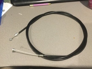
I had a much more successful day today, finding the brake cable I need. I ended up going to Clarence Street Cyclery in Sydney where they had both the brake cable and the cable housing! I was really impressed with their service and amused at when they asked me what kind of bike I needed the cable for, and when I said it’s not for a bike, they were very confused.
Now that I have all the cables, I am almost ready to start construction. All that I need to do now is order the set screws for each of the vertebrae and 3D print the first test vertebrae so I can test my concepts.
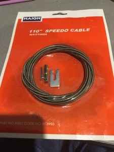
I have had mixed success finding the necessary hardware for the tentacle mechanism. I was able to get the speedometer cable for the tentacle core at a car parts and accessories store in my area, but finding the bicycle break cable has proven to be impossible as there are no bike repair shops in my neighbourhood. I have one break cable in my collection of puppet parts that I can use, but to make the whole tentacle I need seven more. I have found a bicycle repair shop in Sydney CBD that I will try, otherwise I might have to look online.
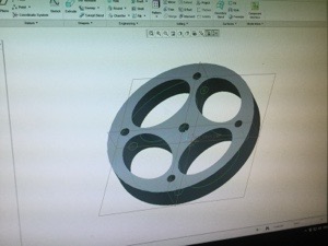
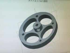
Now that I have the speedometer cable and one of the bicycle break cables, I have started 3D designing the vertebrae. I started by designing a disc that had the holes for the cables marked. Next, I designed the oval passage holes to pull the first stage of cables through the second stage. At the moment, I have two concerns. Firstly, the vertebrae feels too thick dimensionally. The pieces need to be 1/4 inch thick maximum. My second concern is making the passage hole for the set screw that will hold the vertebrae on the core cable. At the moment, the hole is not passing through the stem properly. It could be because the size of the hole is wrong, or the stem is the wrong size.
I won’t know how to solve these issues until I 3D print at least 2 of the vertebrae and test fit them into a tentacle.
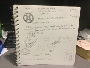
While I was watching the full tutorial on designing and making tentacles from Stan Winston School of Character Arts, I took some notes on how I might proceed to make my cat’s tail tentacle mechanism.
So now I begin the process of sourcing all the hardware required to make the tentacle mechanism. I have to get the hardware first, before I can start modelling and 3D printing the vertebrae. Fortunately, a colleague of mine, made a fantastic suggestion about using bicycle brake cables for the main cables as the cables come with their own housings.
So it is off to Autobarn tomorrow to get the speedometer cable I need for the central shaft of the tail, then I need to find a bike repair shop to get the brake cables I need. I still have to source a few parts like the 16 set screws online but if I can find all the cables on the weekend, I can start 3D designing the vertebrae!
I am about to start my summer school vacation. It has been a challenging year for me teaching and puppetry wise, but now that the year is almost over, I have some time to persue a few of my goals in learning more about mechanical design in puppets.
I have three goals in mind; 1. Design and make a cat’s tail using a cable mechanism, 2. Design and make a rotating eye mechanism, 3. Design and make a sliding control mechanism for blinking eyes. All of these mechanisms already exist in the world but, for me, making them myself will give me an opportunity to explore these shapes and movements and challenge my 3D printing and design experience.
Here are the videos that have inspired me
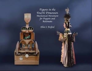
But, this book has been my chief inspiration-
Figures in the Fourth dimension- Mechanical Movement for Puppets and Automata by Ellen S. Rixford