In learning about how Blender works where the user manipulates individual polygons, I have been looking for examples of artists who work with organic 3D modelling and 3D printing to create works of art.
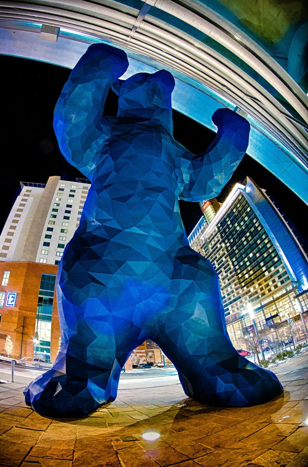
The first reference I came across since learning about Blender was the Big Blue Bear in Denver Colorado USA. The formal name of the artwork is I see what you mean (2005) by Lawrence Argent. The statue is over 12 metres tall (40 feet). It’s surface is covered in triangular polygons and it is blue because the scuptures maquette was 3D printed in blue plastic instead of the original earth tones to represent Colorado.
Big Blue Bear Statue
I have also been watching how Herschel Shapiro creates wall sculptures using 3D printed parts
I have been 3D modelling and 3D printing for many years, but the main program I use, Autodesk Inventor cannot model organic shapes. Inventor is a parametric modelling software so every shape is very precise which makes it fantastic for mechanical puppet parts. However, for the past three years I have wanted to learn how to digitally sculpt more organic, natural shapes such as horns, eyes, noses that are not perfectly symmetrical.
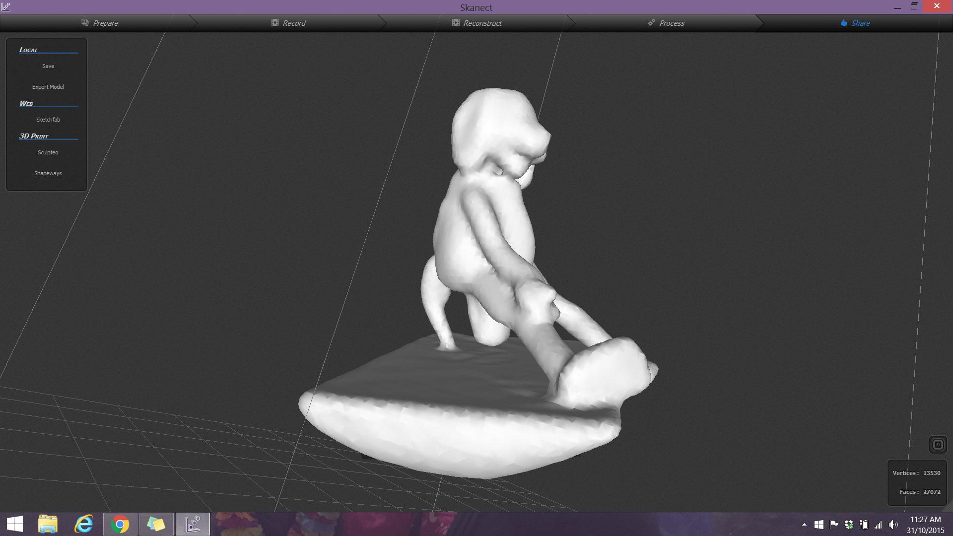
Part of my research has led me to 3D scanning and photogrammetry. Initally, back in 2015 I got to try a handheld 3D scanner that was connected to my laptop by cords called Skanect. The challenge was that there was limited software to edit the scan, and the software that came with the scanner was very difficult to manage.
First attempt at 3D scanning of one of my puppets using a handheld 3D scanner.
In early 2023, I was again exploring new tools for photogrammetry which is a form of 3D scanning using lots of individual photos, and a prop making channel I follow, gave a demonstration of a mobile app they used to make a space helmet. The demonstration they gave led me to trying the Polycam app for iPhone.
I tried the app and the paid version worked great for a small puppet part that I needed. The trick with this app is that you need to walk around the object, so it is important to place the item being scanned on a stool or stand that you can walk around.
My next step was to find a software package that I could edit the scan in. In 2021, I tried Z Brush, but I found that software package was very expensive and difficult to navigate as a first time user. It is also a software package that was not available at school- so if I learned the software, I could not share it with students. Since I have access to the Autodesk suite of products, fast forward to 2022, I started to explore Autodesk 3DS Max. Working through the training from Linkedin Learning, my experience was this software was more focused on building environments rather than characters.
Now in 2023, I have just attended a workshop called Digtal Tools for Analogue Makers taught by Philip Millar (@puppetryschool) at the Melbourne Festival of Puppetry on July 1, 2023. In the pre-workshop reading, Philip not only recommended Polycam as one of many 3D scanning tools, but also Blender as the modeling software. Blender is a free, open source program that is very similar to ZBrush in it’s capabilities, and it is available for the computers at school! I found an incredible YouTube video on how to use Blender with a drawing tablet to help me learn the program very quickly.
Early stage sculpting of a UV sphere in Blender
Late stage sculpting of a head following the YouTube tutorial
Polycam scan result
Importing the Polycam scan into Blender.
Final sculpt in Blender side by side with the original sample.
3D printed version from Blender next to the original puppet nose
One of the most challenging steps was removing the background surface from the scan result without damaging the scanned part I required. Each polygon had to be individually deleted.
The resulting mesh was only the surface of the puppet nose- there was no thickness that would support a 3D print. I had to learn how to add the back by closing the mesh, then began a process of refining the mesh and smoothing the polygons. I completed the process by adding a rectangular prism to the mesh and aligning it to flatten the back. It meant I had to install an add on called Booltools.
I have curated a playlist of YouTube videos and websites I found helpful in the past week as I have been trying ideas to achieve my goals.
I really struggled with orienting the mesh so that I could use the grab and smooth tools symmetrically. It is something I still have to learn more about. In all, I am really excited by what I can now do with Blender.
To make Totoro’s ears/ horns, I modeled the ears using 3 modelling and printing. Due to the scale of the piece, I had to try to cut the horn into 3 pieces. I had a great deal of difficulty in splitting the shape in that I am still not familiar with breaking a model up in Creo Parametric 3.0. I was able to make the bottom two pieces quite easily, but making the top pointed part fit proved to be very difficult to make the right size. I ended up achieving a satisfactory result after lots of failed attempts. I definitely need to learn an alternative approach to making a 3D model that breaks up into interlocking pieces.
To cover the ear with fur, I put the ear into a freezer bag, and covered the bag with small pieces of tape. I then used a small pair of embroidery scissors to cut the tape and plastic off and cut lots of small darts to create a flat shape. The flat shape then became the pattern for cutting the fur. I did add a 3mm seam allowance while cutting the fur so I could hand sew the fur together and turn it over the 3D printed form. The ears/ horns were then sewn around the base onto the fur.
Fur covered, 3D printed ear forms with pattern.
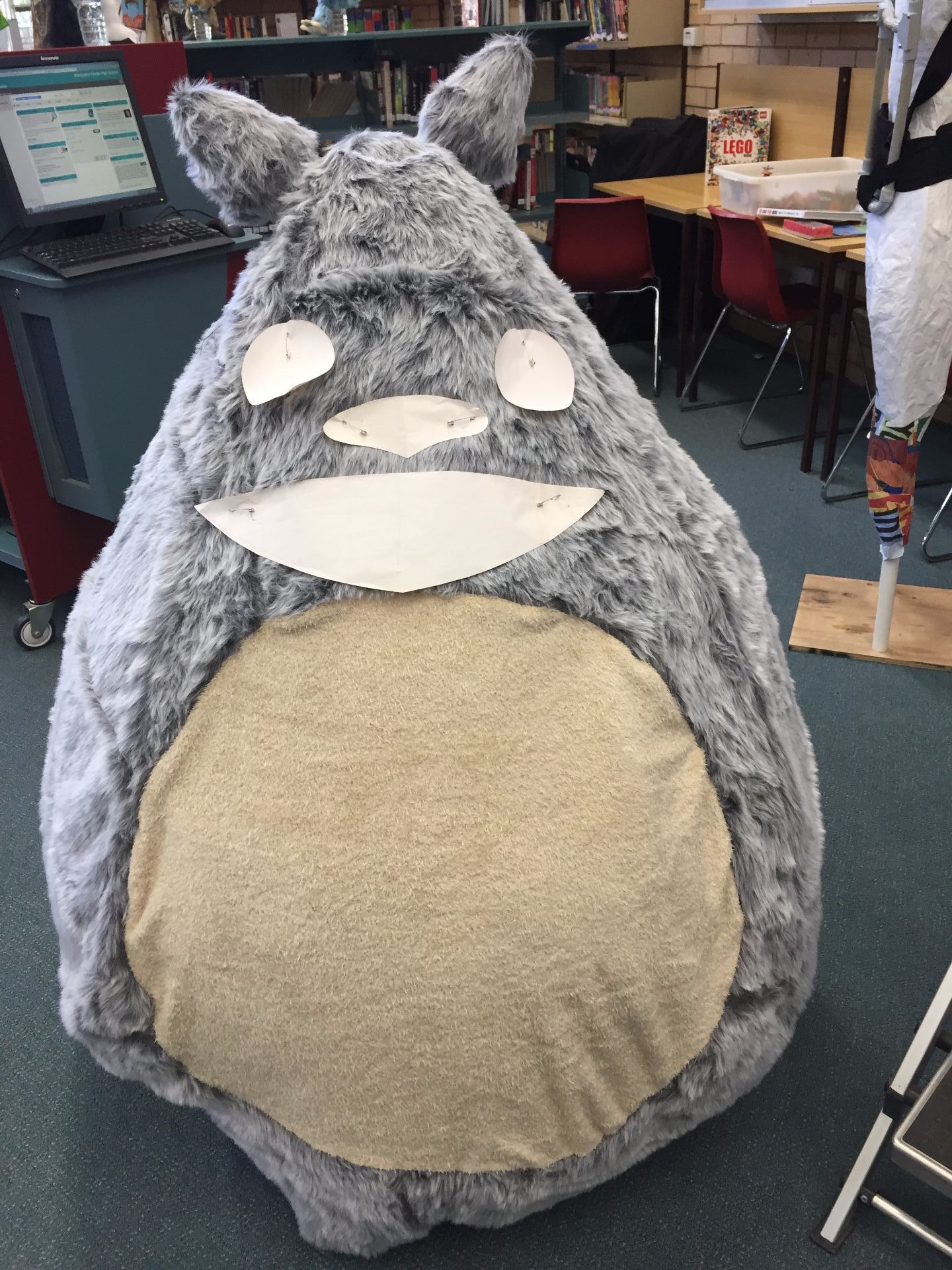
I used more butcher’s paper to create the shapes of the eyes, nose and mouth so that I could experiment with sizes and placement.
Planning the facial features of Totoro
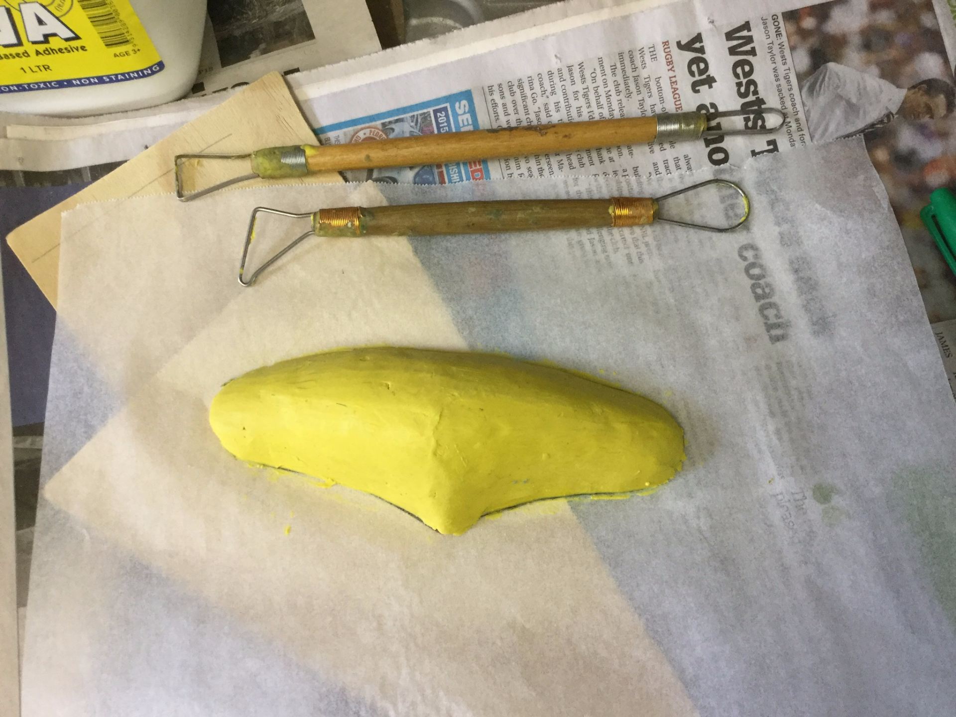
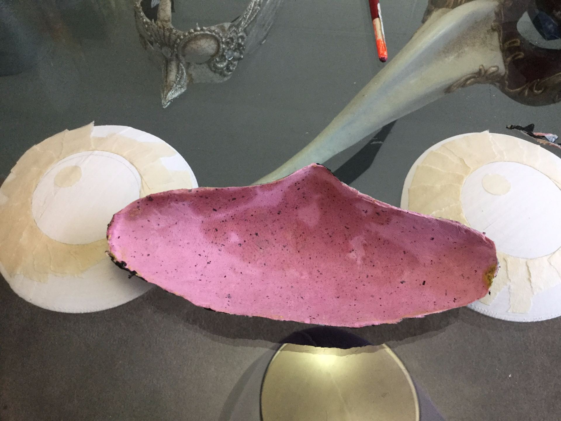
To make the nose, I used the butcher’s paper template as a guide to the overall size of the nose and built plasticine up on it. I then used four layers of my own hand made paper to cover the nose form.
Sculpting the nose form from Plasticine.
I created the eye forms by modeling them on the computer and printing them out using the 3D printer. I then used black acrylic paint to create the pupils.
3D printed eyes ready for painting with the painted papier mache noseInside of the papier mache nose with the 3D printed eyes.
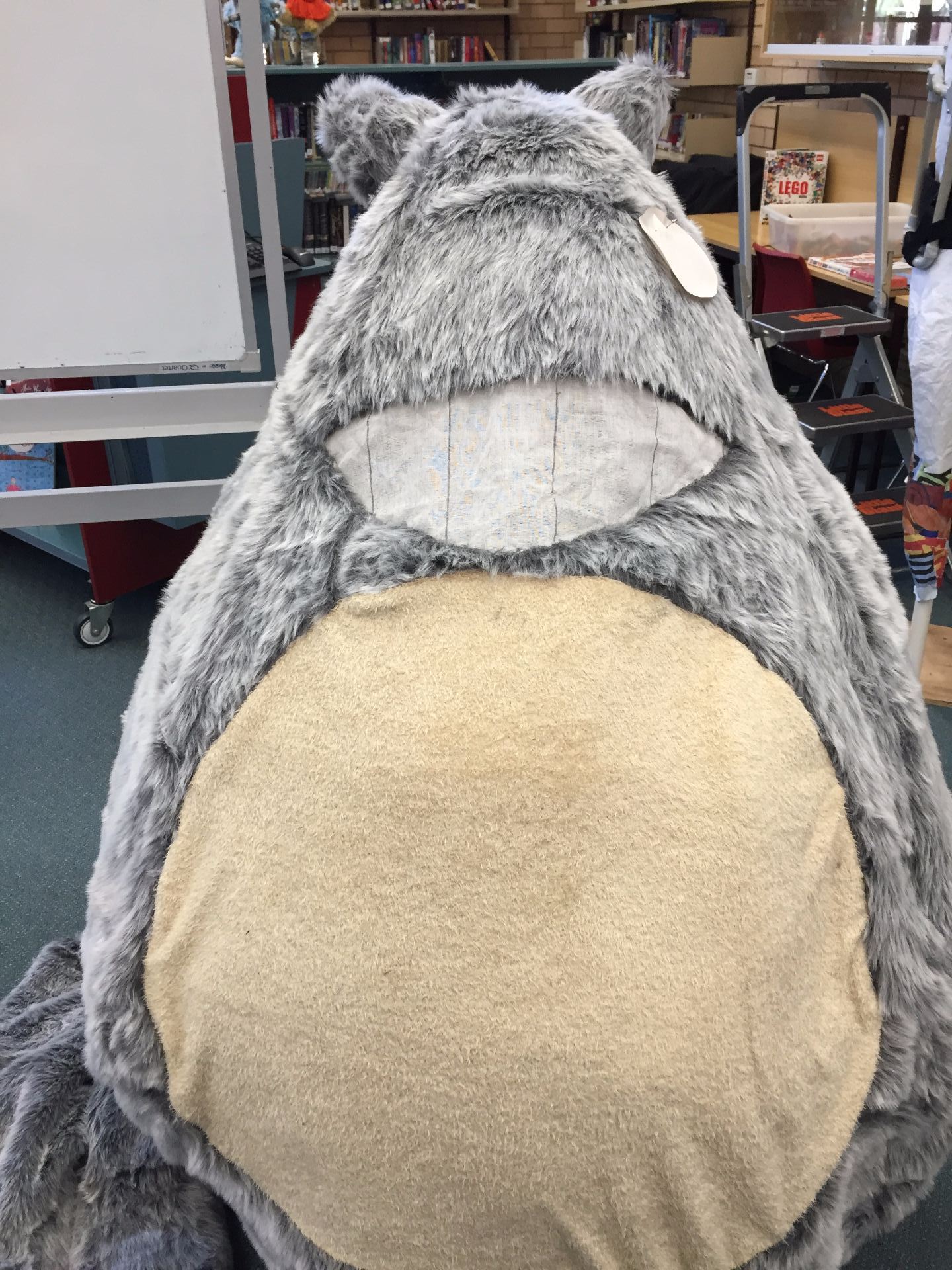
The mouth of Totoro is how I see out of the puppet. I originally used three layers of curtain netting, but it was too hard to see out of, so I removed one layer.
Totoro’s teeth were drawn onto the mesh using a black Sharpie.
Mouth opening covered with white mesh curtain fabric.
To make Totoro’s whiskers, I used long, black zip ties. To attach them to the face, I cut a small slit into the fur using embroidery scissors. Then, I inserted the square end of the zip tie and glued it in place using hot glue.
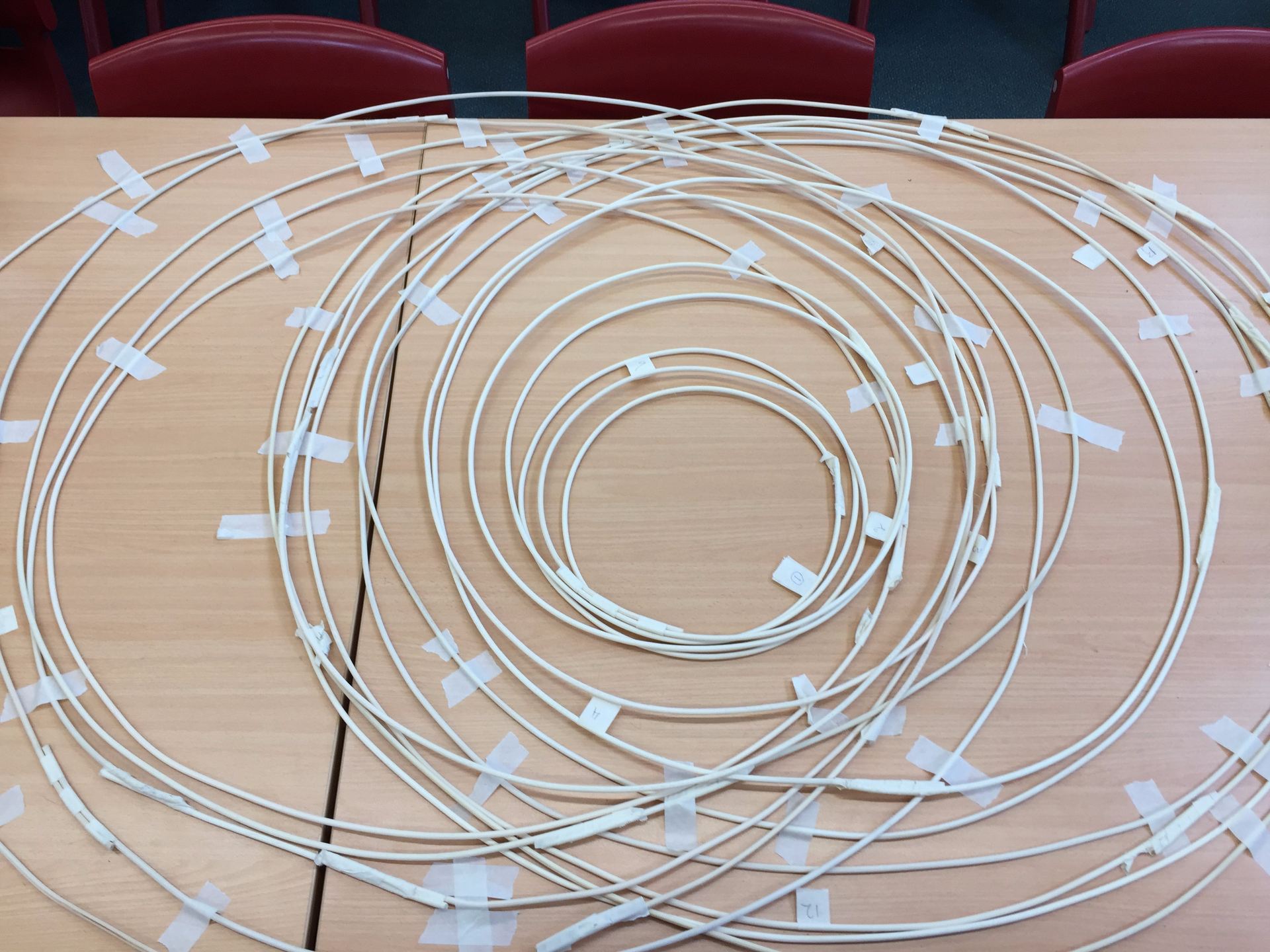
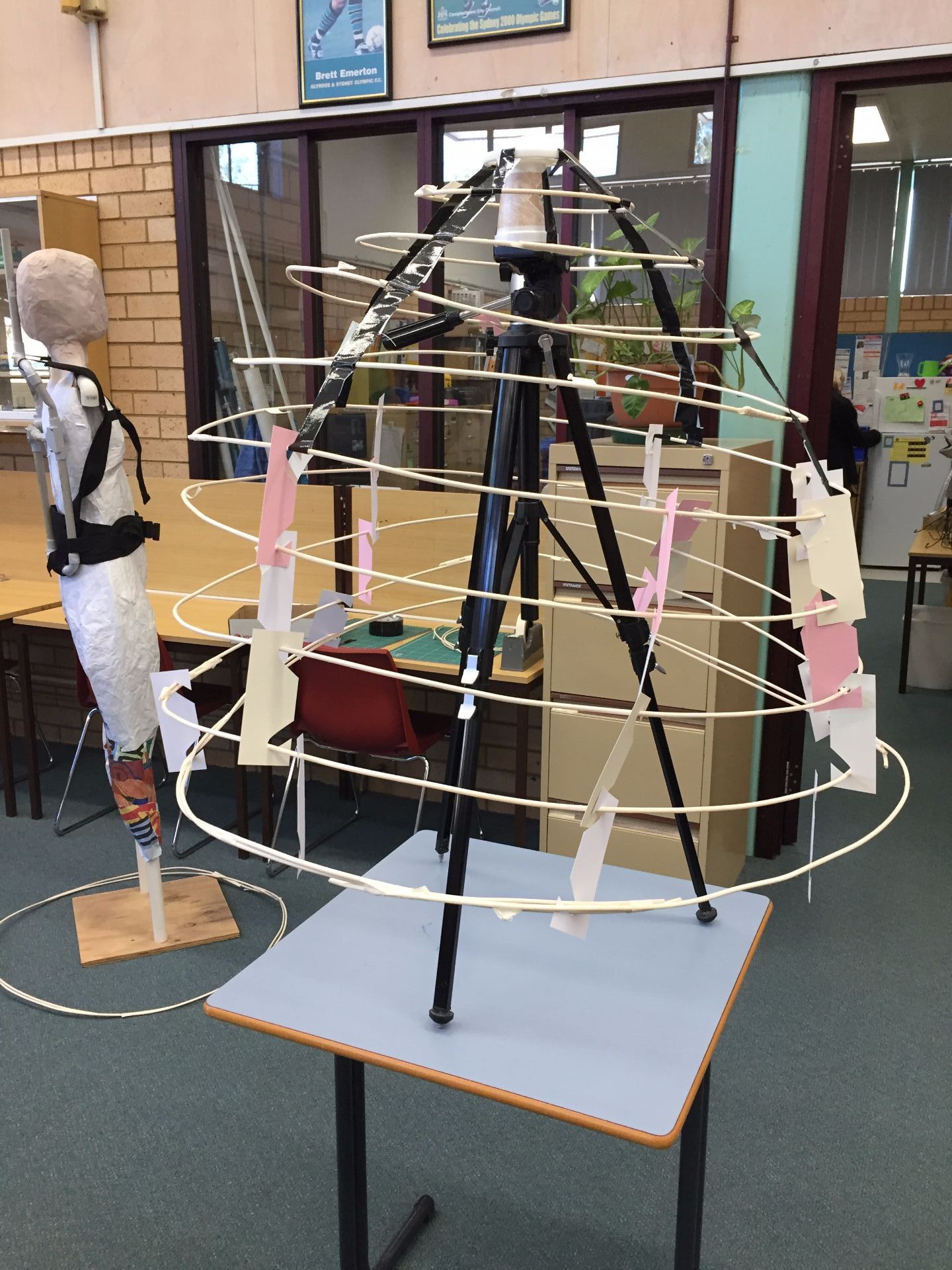
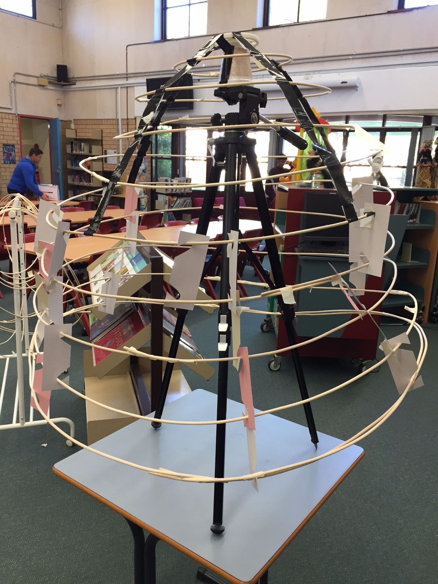
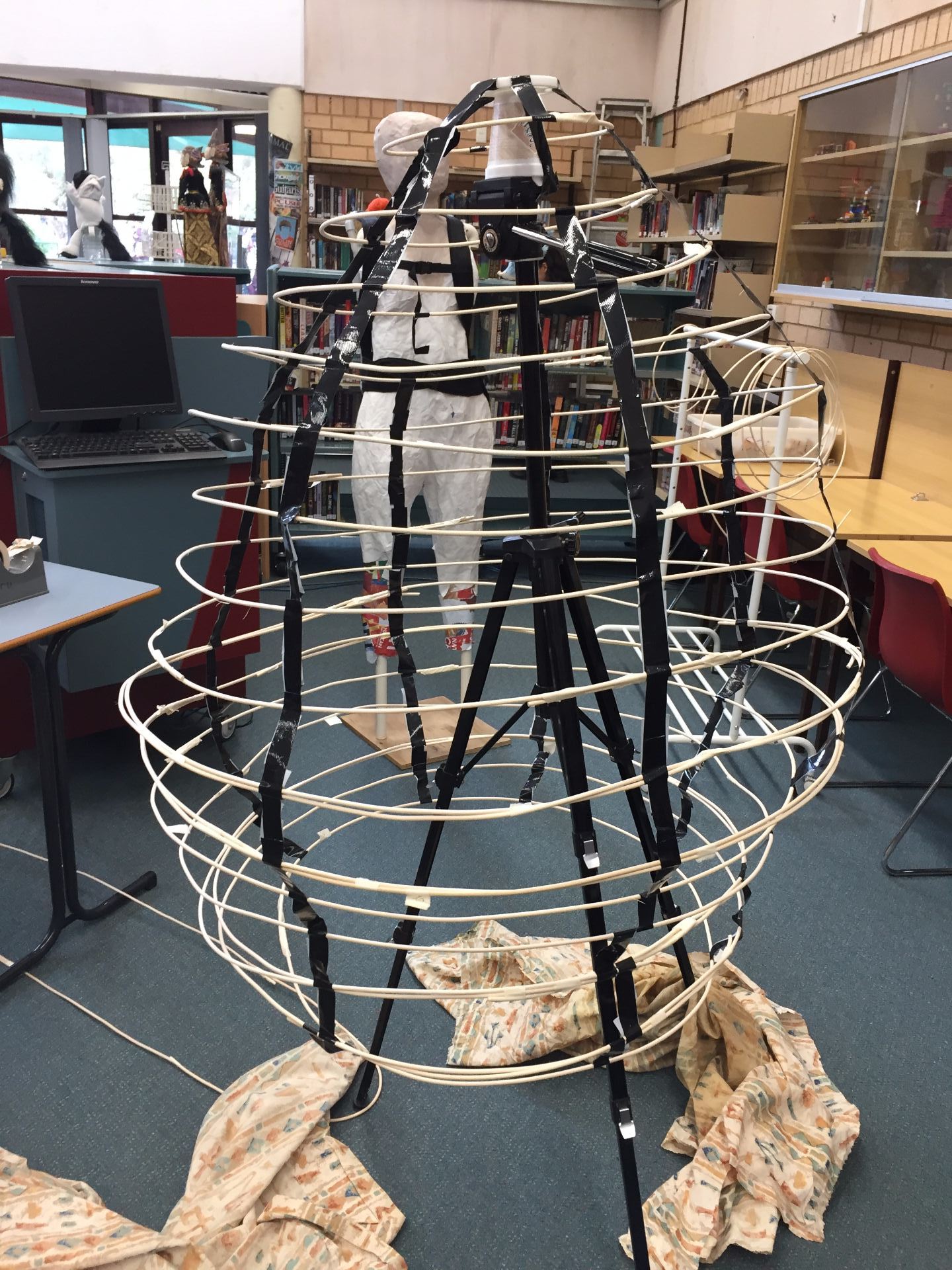
The next phase of the construction was to make the concentric rings that are the skeleton of Totoro. Using the calculations I made with the full size plan, all 16 rings were created by measuring the length of the circumference, adding a palm width of cane for overlap and using masking tape to hold the ring closed.
Trying to flatten the cane rings
I did run into several issues with the cane. When it arrived, the cane was very tightly coiled. When creating the largest rings, the rings would distort and not lie flat. We tried putting the rings under weights overnight, which did help some of the rings to lie flat-ish. Some rings also responded to hand manipulation of forcing the cane to bend in the opposite direction, but we always risked snapping the cane.
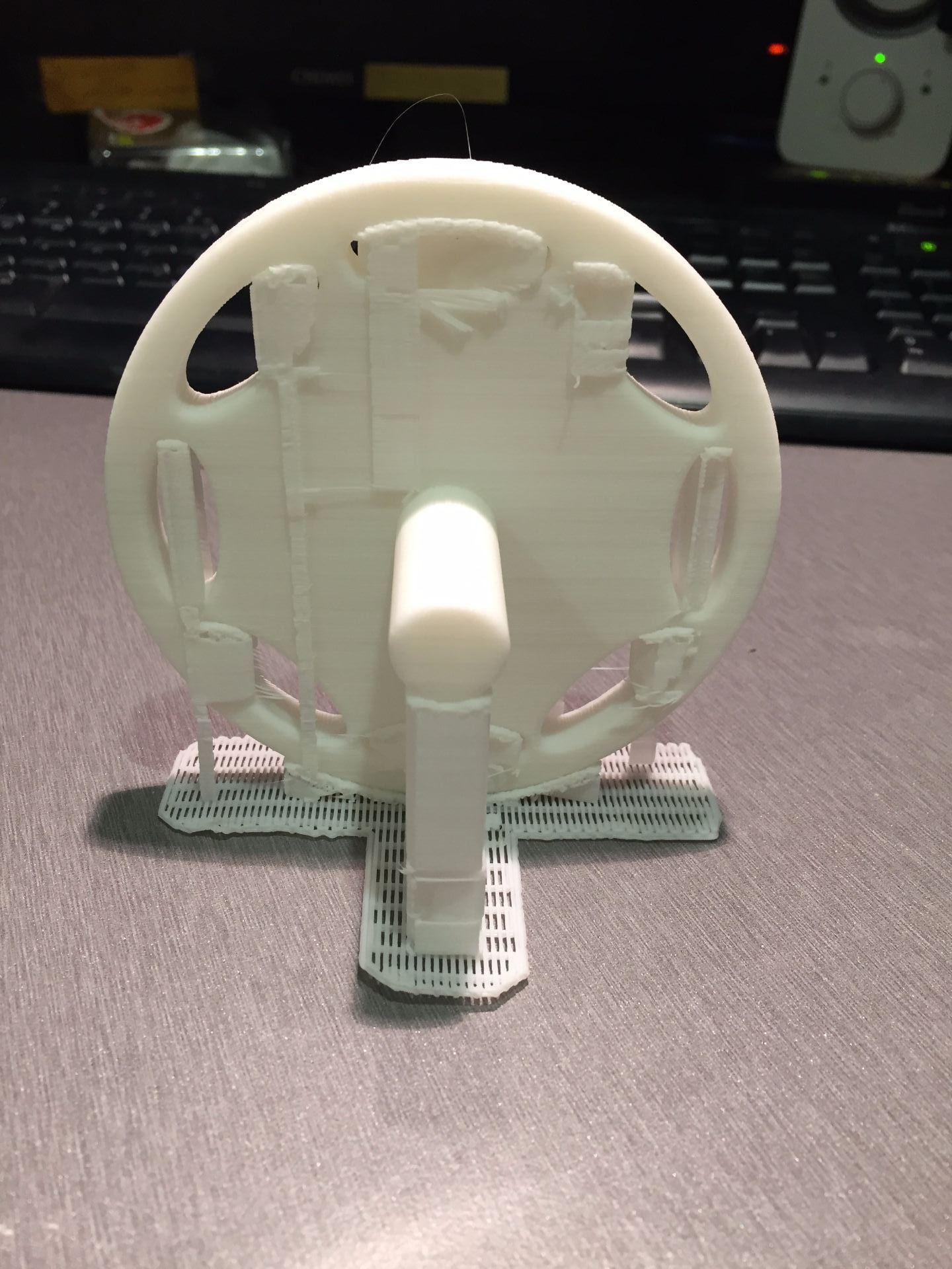
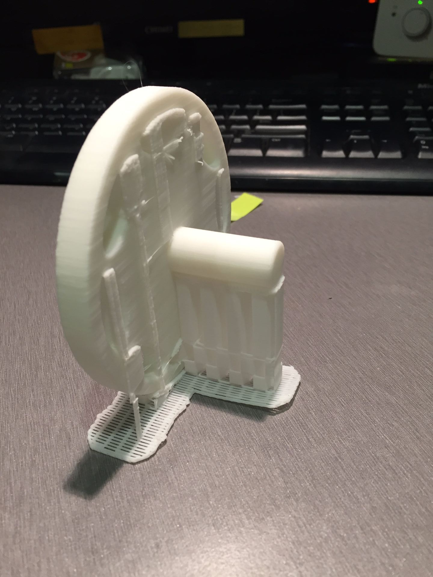
The other challenge I had to address was how to suspend the cane rings from the backpack frame. Adam Savage used a wooden ring bolted to his backpack frame. I don’t have access or expertise in using wood to make a ring, but I do have access to 3D design software and a 3D printer. I designed a circular disc with a section that inserts into the pvc mast. By using gaffer tape, the rings are suspended from the main disc.
All I can say is wow! It works- it’s alive!!!!! I have 16 vertebrae and 8 are moving precisely like they are supposed to! Stage 1 of the tentacle- from the tip to vertebrae 9 is moving and curling. However, for some reason, stage 2 is barely moving. Current working theory is that the brake cable housing I am using is too stiff to allow the stage 2 mechanism to move at all. I may have to make another base plate that has no large passage holes and screw all the brake cable housings into that so that the bare cable is running through the passage holes of the actual tentacle.
I am still waiting for more set screws to arrive so I can finish attaching all the vertebrae and the tail tip. While I am waiting, I have started designing the next mechanism!!!
I have started assembling the tentacle! After printing one of the vertebrae, I held it up to a puppet that it could be used for, and I found that the diameter of the vertebrae was too wide. So I reduced the diameter on the original model to 1.5 inches, reconverted it to metric and printed 12 vertebrae. For the tip, base and vertebrae 8 & 9, where the cable housing had to be inserted or the cables terminated, I had to adjust the design so that the holes were 4mm in diameter.
Each vertebrae holds onto the central speedometer cable using a 10/32 by 0.25″ set screw. I had the drill and tap each hole to be able to thread the set screws. I am now waiting for more set screws to arrive, then, I will be able to thread through the outer cables and hopefully this tentacle will start moving!
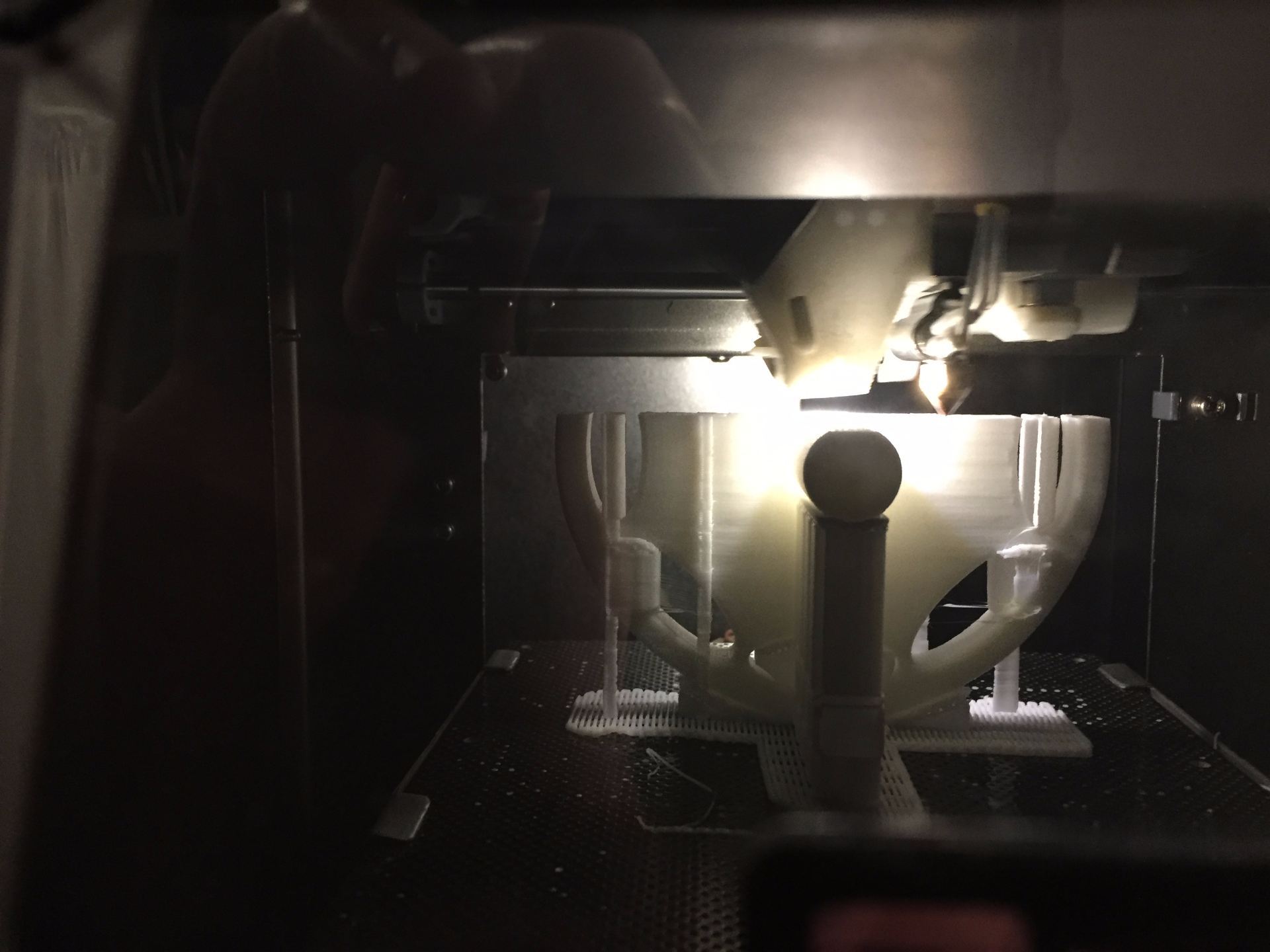
Today I tried to print the first of the vertebrae. When I imported the design into the UP Studio software, the vertebrae appeared incredibly small. I designed the vertebrae to be 1.75 inches in diameter and the main ring is 0.25 inches high, but in the UP Studio software, the design was 1.75mm wide!
I consulted with a more experienced colleague of mine and together, we discovered the problem. UP Studio software cannot distinguish between imperial and metric measurements. It can only read in metric, so when I imported my design in imperial measurement of 1.75 inches, it read it as 1.75mm. I had to convert the design parameters to millimetres in the software I use to design 3D objects and then re-import the file into UP Studio. Finally the design could be printed!
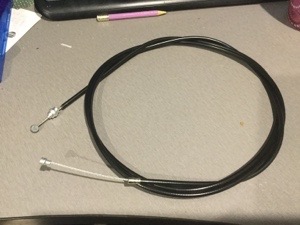
I had a much more successful day today, finding the brake cable I need. I ended up going to Clarence Street Cyclery in Sydney where they had both the brake cable and the cable housing! I was really impressed with their service and amused at when they asked me what kind of bike I needed the cable for, and when I said it’s not for a bike, they were very confused.
Now that I have all the cables, I am almost ready to start construction. All that I need to do now is order the set screws for each of the vertebrae and 3D print the first test vertebrae so I can test my concepts.
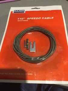
I have had mixed success finding the necessary hardware for the tentacle mechanism. I was able to get the speedometer cable for the tentacle core at a car parts and accessories store in my area, but finding the bicycle break cable has proven to be impossible as there are no bike repair shops in my neighbourhood. I have one break cable in my collection of puppet parts that I can use, but to make the whole tentacle I need seven more. I have found a bicycle repair shop in Sydney CBD that I will try, otherwise I might have to look online.
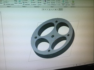
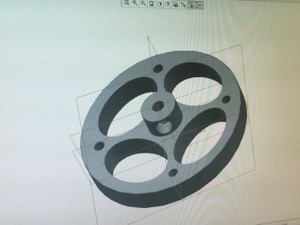
Now that I have the speedometer cable and one of the bicycle break cables, I have started 3D designing the vertebrae. I started by designing a disc that had the holes for the cables marked. Next, I designed the oval passage holes to pull the first stage of cables through the second stage. At the moment, I have two concerns. Firstly, the vertebrae feels too thick dimensionally. The pieces need to be 1/4 inch thick maximum. My second concern is making the passage hole for the set screw that will hold the vertebrae on the core cable. At the moment, the hole is not passing through the stem properly. It could be because the size of the hole is wrong, or the stem is the wrong size.
I won’t know how to solve these issues until I 3D print at least 2 of the vertebrae and test fit them into a tentacle.
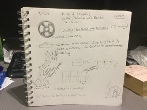
While I was watching the full tutorial on designing and making tentacles from Stan Winston School of Character Arts, I took some notes on how I might proceed to make my cat’s tail tentacle mechanism.
So now I begin the process of sourcing all the hardware required to make the tentacle mechanism. I have to get the hardware first, before I can start modelling and 3D printing the vertebrae. Fortunately, a colleague of mine, made a fantastic suggestion about using bicycle brake cables for the main cables as the cables come with their own housings.
So it is off to Autobarn tomorrow to get the speedometer cable I need for the central shaft of the tail, then I need to find a bike repair shop to get the brake cables I need. I still have to source a few parts like the 16 set screws online but if I can find all the cables on the weekend, I can start 3D designing the vertebrae!